Catchcam: Choosing Components
Lets choose major hardware components for the Catchcam project. As I’ve written before, the idea is to have a plug and play device that alerts if the vehicle is approaching a speed camera both via sound and LED signal.
Catchcam draws power from built in USB-C socket that is connected to a vehicle USB socket. As for the user interfaces, it has a small speaker, a volume potentiometer, System status LED, GPS signal status LED, Camera alert LED, and a Software update button (more on that later). In order to know the current position, Catchcam has GNSS module with an on-board Antenna. Moreover, to reproduce audio alerts, Catchcam incorporates DAC, Low-pass anti aliasing/reconstruction filter, and an Audio amplifier.
Note: If you’re interested, you can pre-order a sample at vnucec.ivan@gmail.com.
Lets go through the components one by one.
Components
Microcontroller and Flash
First we will choose the microcontroller. Initially, I was thinking about choosing one of the STM32F microcontrollers such as STM32F407 for example, with the hardware FPU, but the prices are astronomical, and in my opinion, there are better and cheaper alternatives. Futhermore, the STM onboard Flash memory is around 1MB max., which might be too low for us in order to store more than all the camera positions along with audio samples. In order to incorporate all of that, I would certainly need additional external flash which would increase the cost and complexity of the design.
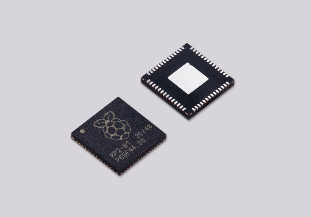
The decision has been made on the popular rp2040 microcontroller from Raspberry Pi Ltd. I’ve really liked this option because it features flexible I/O with dual-core Arm Cortex-M0+ processor, 264 on-chip SRAM, and best of all - Drag-and-drop programming using mass storage over USB. I love the idea that you can simply update the software by just drag-and-dropping already built firmware, which is ideal for project because an ease of updating camera positions is a must! You don’t need any external hardware or software to update, nor you need any special computer knowledge. It’s as simple as using an USB drive stick.
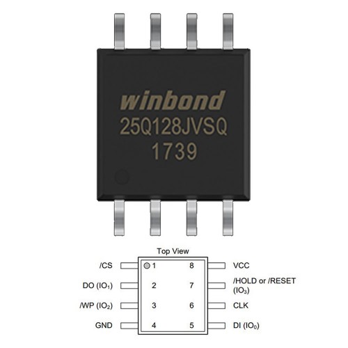
The software resides on the W25Q128JVSIQ external 16MB flash chip, which is a plenty of storage for all the camera positions and audio samples (which populates most of the flash) along the software.
GNSS Module and Antenna
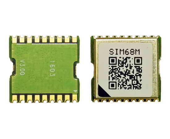
The second major part of the project is a GNSS module. I’ve searched for a low cost solution and stumbled on the SIM68M module from SIMCom Wireless Solutions Co.,Ltd. I’ve also seen u-blox ones, but I havent taken them into consideration because I’ve had good experiences with the SIMCom modules in the past. SIM68M features an in-built LNA amplifier with support for the active GNSS antenna. Futhermore, SIM68M supports all of the major GNSS satellite constellations so the device can work across the globe.
The second important factor is the GNSS antenna. I’ve spent great deal of time searching one. The idea is that the Catchcam would reside on the vehicle’s dashboard with the clear view of the sky in order to achieve best signal reception.
There are several antenna options to choose. There are two major divisions of the GNSS antenna types: active and passive. The difference is that the active antenna has build in LNA amplifier with the SAW filter in order to amplify and filter signal. Passive antennas lack those features. In the high-noise/low-signal scenarios, the active antenna is recommended. In my case, with the clear wive of the sky, and with the GNSS module build-in LNA amplifier, I’ve chosen the passive antenna type. Moreover, I’ve heard that there might be a problem if you use both the active antenna and in-built LNA because there might be an over-saturation of the signal, but I’m unsure of the claims because GNSS signal is rather weak anyway.
Besides active and passive ones, GNSS antennas comes in different packages and I will name a few. There are PCB Patch antennas, Ceramic Chip antennas, Ceramic Patch antennas, and Helix antennas. Helix antennas have good signal reception regardless of its orientation, and it is popular in a hand-held devices. However, Helix antennas are rather small in size, and the size is an important factor. The larger the antenna, the more signal amplification it has (with respect to the dipole antenna). Ceramic chip antennas are compact solution for mobile devices but they are too rather small. PCB patch antennas are good choice because you don’t need to incorporate another part, however I’m not sure how good they are in terms of signal amplification.
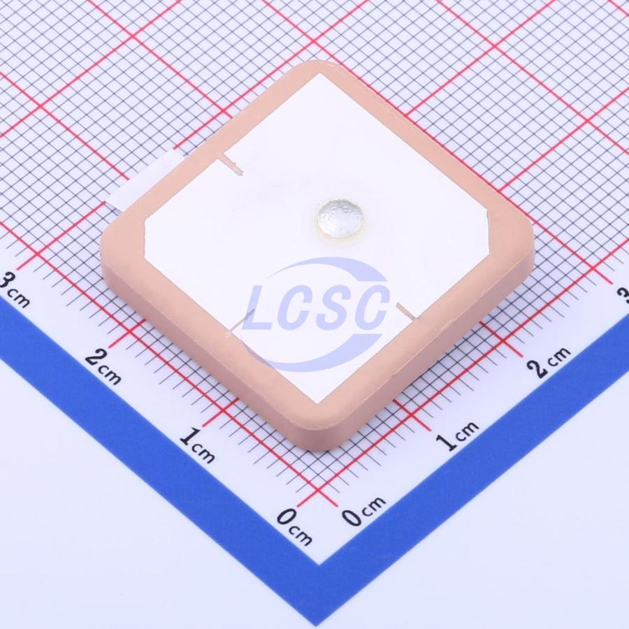
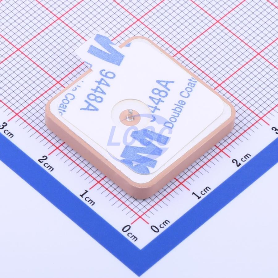
As Catchcam is not hand-held, nor particularly small, I’ve chosen to go with the KH-GPS252504-WY Ceramic Patch antenna. It’s 25x25 mm in size, and it has a good signal reception. However, it needs to have large ground plane (about 50x50 mm is fine) in order to work properly.
Audio
Speaker
The next comes the speaker with it’s owm audio reproduction circuitry. I would like to power the speaker from the USB 5V VBUS. With the 500 mA VBUS current limit (defined by the USB standard), we can theoretically have max. power of 2.5W (5V * 500 mA), so 1W speaker might be enough in our case. I’m unsure about sound level at 1W, but we’ll see. I’m afraid that the user might miss the camera alert if they are listening to loud music for example.
There are variety of speakers out there: from the physically large ones with good audio spectrum characteristic especially in the low frequencies bass tones, all the way to the small Trough-hole or SMD speakers. With the regards to the smaller ones, there are ones with the external power leads so you can mount them directly to the enclosure, and there are trough-hole/SMD ones that can be soldered directly to the board.
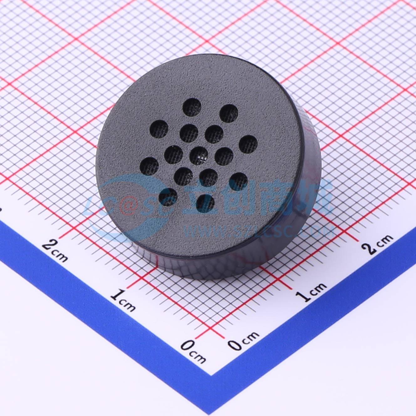
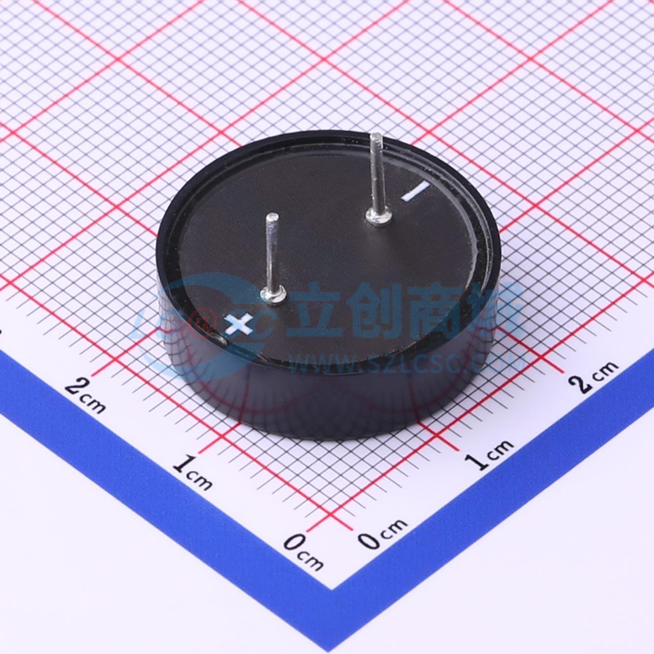
I’ve chosen the GSPK2307P-8R1W trough-hole, 1W, 8 Ohm, 88 dB speaker. It’s 23 mm in diameter and 6.8 mm in height. I’ve also considered the SMD ones but they are rather expensive compared to the trough-hole ones.
Audio Amplifier
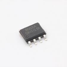
The speaker is driven by the Audio amplifier that is powered by the filtered VBUS voltage. I’ve stumbled on the popular and design-proven LM358 but I have dropped the idea because the signal input has to be biased. Being intrigued by Did I make the cheapest DIY amplifier? video that references cheap chinese FM8002A audio amplifier, I’ve chosen it for audio amplifier. It can deliver 1.5W power to the 8 Ohm load, handle 5V power supply, the input signal doesn’t need to be biased, and it has adjustable gain which enables volume control. It also features a Shutdown mode which mutes the output which I like because I’m afraid that the noise could creep onto a signal trough the USB car connection.
DAC and Reconstruction filter
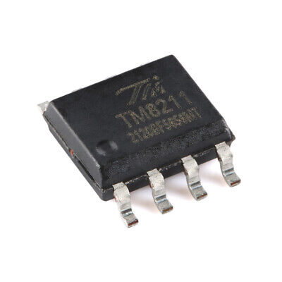
The audio amplifier input signal is generated with 12-bit TM8211 DAC and Low-pass Anti-aliasing/reconstruction filter (Sallen-Key topology). TM8211 is cheap chinese PT8211 knockoff. The data from the microcontroller comes over I2S bus to the DAC, which is referenced to the filtered 5V VBUS. That all results in a 0.0-2.5 V signal swing at the DAC output.
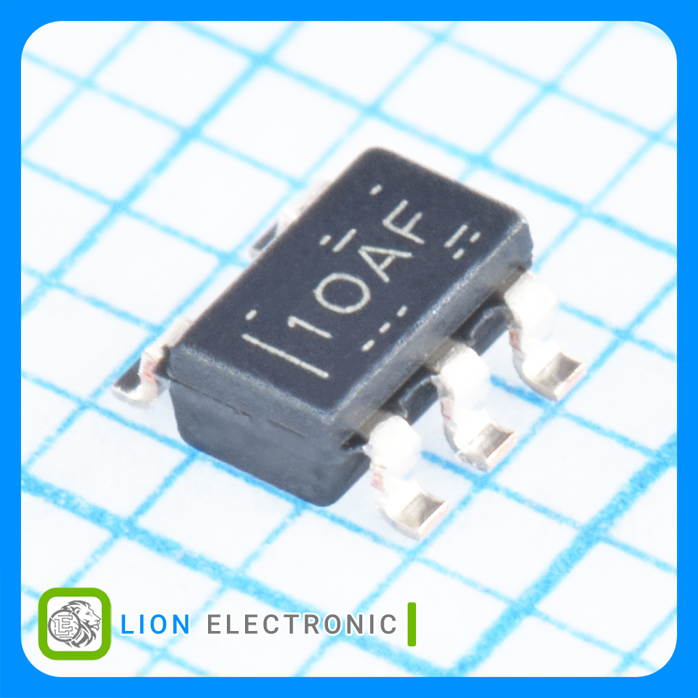
Audio samples are sampled with 44.1kHz frequency rate. Signal from the DAC output is then reconstructed with the active Low-pass filter with a cut-off frequency set to about half of the sampling frequency. For the active filter, I’ve chosen TLV9061IDBVR OP-AMP because it is a rail-to rail amplifier that can be powered with the 5V. Gain of the Low-pass filter is set to 1. I will write about signal generation and filtering in another post.
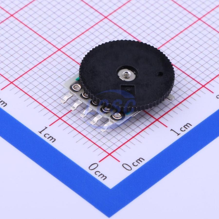
I’ve also incorporated RK10J12R0A0B knob type potentiometer so the user can set the audio volume. The potentiometer resistance directly affects the audio amplifier gain so the signal to the speaker can be reduced all the way to the zero.
User Interfaces
USB-C Connector
As for the USB connector, I’ve chosen standard USB-C (USB v2.0) SMD connector at a 90 degree angle. Also, I’ve added the NCP361SNT1G USB Over-voltage and Over-current protection IC, and added the USBLC6-2SC6Y ESD protection to protect the VBUS and data lines from static discharges.
LEDs
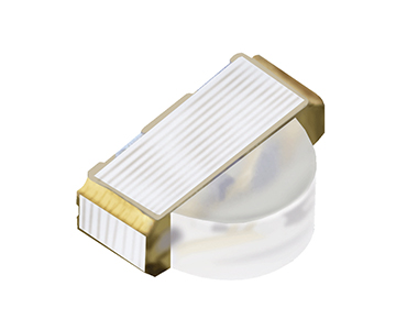
Both the System status LED and GNSS Signal status LED, I’ve chosen 12-22SURSYGC/S530-A2/TR8 90 degree angle SMD led that encapsulates both Green and Red LED in the same package. The idea is that the System status green color LED blinks periodically, and if some error happens, it becomes red.
Similarly, the GNSS signal status stays green as long as the GNSS data is valid, and if signal is lost, it becomes red. As for the Camera detected LED, I’ve chosen TJ-S3210SW5TGLC6B-A5. It’s also 90 degree angle SMD LED but with a blue color. The driving current for the Camera detected LED is somewhat higher at 10 mA in order to be visible even under daylight sun.
Software Update Button
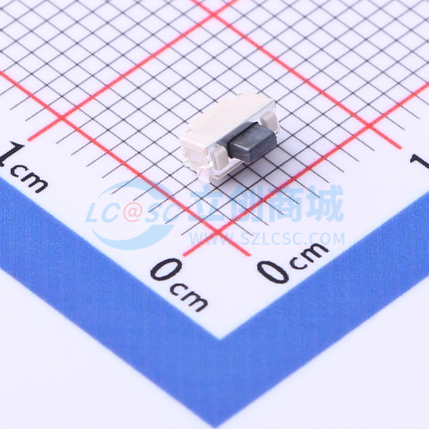
And lastly, there is a small TSA002A3518B 90 degree angle push-button that enables software updates. The idea is that the user can easily update its device firmware by connecting it to a PC and simply drag-and-drop the new firmware. In order to do that, the button needs to be pressed while the user connects USB cable to a PC. This would then trigger the in-built rp2040 USB mass storage bootloader which would then present the microcontroller storage as a USB mass storage media device and enable firmware drag-and-drop feature.
Power Supply
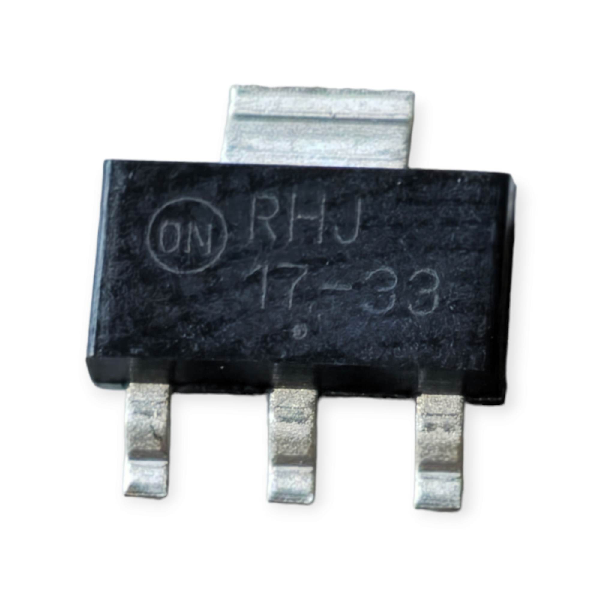
The 5V comes from the USB connector to the NCP1117ST33T3G 3.3V, 1A fixed voltage linear regulator. The 3.3V is then distributed to the microcontroller, and GNSS module. The 5V is then filtered with the simple CLC (PI) filter and then distributed to the DAC, Low-Pass filter, and finally to the audio amplifier. Audio filtering will be discussed in another post.
Conclusion
And that is basically it when it comes to the components. We’re left with the passive components that will not be discussed.
Future considerations
I’ve thought a lot about incorporating so the device can be mounted on a vehicles that are lacking USB ports such as old vehicles or motorcycles, but I’ve dropped the idea for now because I don’t want to drop design simplicity in the project prototype phase. I’ve also been thinking about incorporating GSM module so the devices can automatically update its software, but that was also dropped because of the complexities involving a server that would enable those updates. Also I would need to have SIM cards that works across the globe, and with different internet providers… Just not worth it for now.
Note: If you’re interested, you can pre-order a sample at vnucec.ivan@gmail.com.

