Catchcam: Designing Audio Circuitry
In this post, I will be discussing the audio circuitry of the Catchcam. The audio circuitry is responsible for converting the digital audio data from the microcontroller into an analog signal that can be played through a speaker.
Note: If you’re interested, you can pre-order a sample at vnucec.ivan@gmail.com.
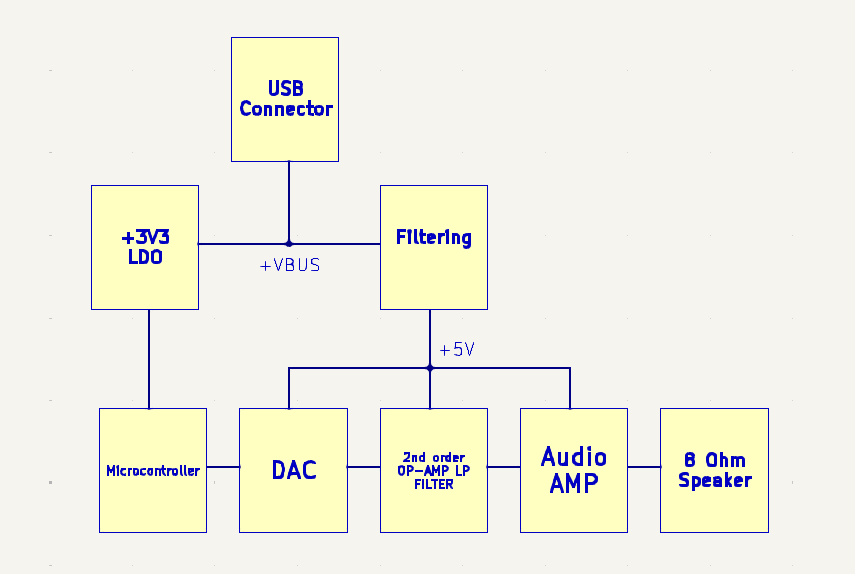
Below is a block diagram of the audio circuitry of the Catchcam:

The audio circuitry consists of:
- power supply filtering,
- digital-to-analog converter (DAC),
- anti-aliasing (reconstruction) filter (AAF),
- audio amplifier, and
- speaker.
Let’s discuss each of these components in detail.
Power Supply Filtering
When designing an audio power supply, it’s important to ensure a clean and stable power source. In this case, the power supply needs to be at 5 volts and will be sourced from the USB connector (VBUS), which is connected to a vehicle’s USB port.
However, vehicle USB ports can be a bit noisy, so we need to filter out this noise before it reaches the audio circuitry. A common approach that I’ve seen on the internet is to use a PI filter.
Avoiding Ferrite Beads
Many PI filter designs online utilize a ferrite beads to prevent digital power rail ripple. However, I’ve read here and here that ferrite beads can actually amplify noise at certain frequencies and are not recommended for new designs, regardless of how popular they are.
Instead, I decided to use a MLP2012H2R2MT0S1, 2.2 μH inductor in a small 0805 package rated at 1 amps.
Calculating the Capacitor Values
I spent a lot of time finding the right capacitance values, but on the same post above it was written: “Overall, if the filter performance is not critical, don’t spend your time overanalyzing it”. This have had me realized that the exact values of the capacitors doesn’t matter that much, as long as they’re in the right ballpark.
One thing to be careful about is the USB bus input capacitance because it is restricted by the USB specification to maximal 10 uF. However, I’ve placed more than 10 uF in parallel in order to increase the filtering. It can be done in my case because I have added an inrush current limiting IC connected to the VBUS line (see my older blog post about choosing components).
The Final PI Filter Design
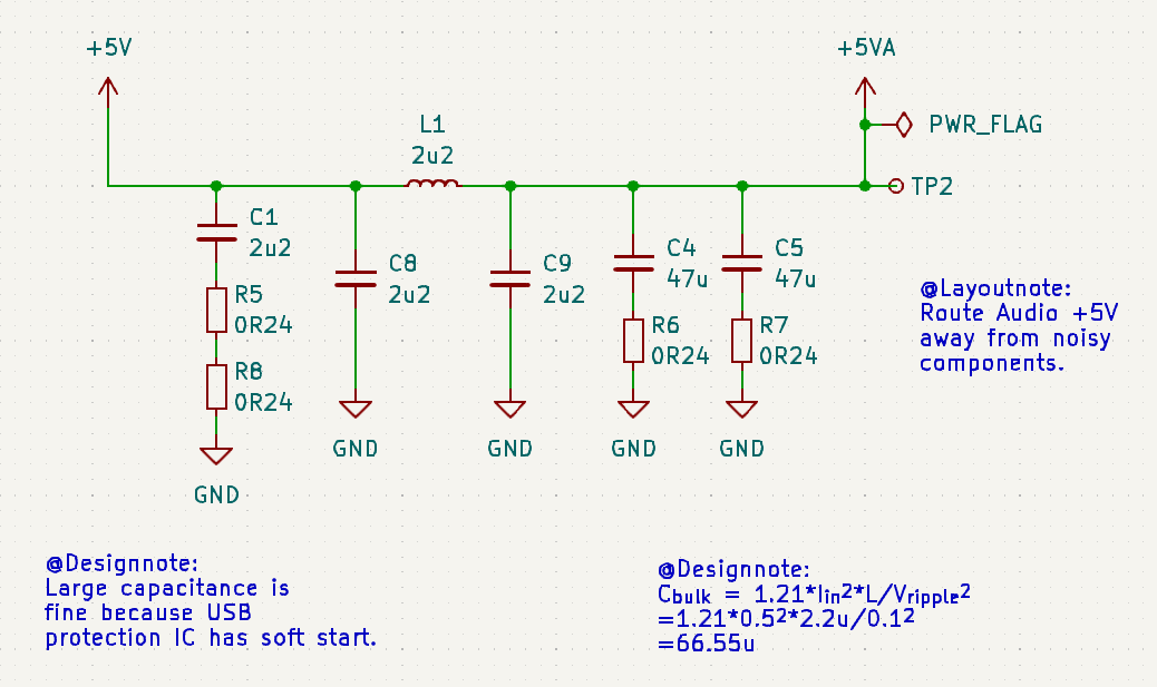
So, here is the PI filter I ended up with:

This filter should effectively remove the noise from the vehicle’s USB port, providing a clean 5V power supply for the audio circuitry. I’ve also added a test point to measure the voltage ripple but I haven’t measured it yet.
You may ask why there are multiple 0.24 Ohm series resistors? The series resistors provide additional damping and help with stability of the filter because ceramic capacitors have quite low ESR values compared to the Electrolytic caps. Why two 0.24 Ohm in series and not one 0.58 Ohm you might ask? Because I want to reduce bill of materials. You will see it in other parts of the schematic as well.
Here is a video from MicroType Engineering that I’ve found useful. It explains the design of the PI filter on a real world example. Also, this document from Texas Instruments explains the damping in more detail.
I also want to mention this blog post from Andy Brown, where he explains the USB filtering in more detail with beautiful oscilloscope graphs.
Digital-to-Analog Converter (DAC)
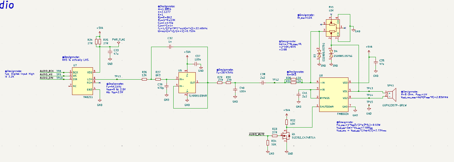
The DAC is responsible for converting the digital audio data from the microcontroller into an analog signal. I’ve chosen the TM8211 DAC which is chinese version of PT8211 DAC. It’s a 16-bit two-channel DAC with I2S interface. Because it’s R-2R type, the output voltage swing is from 0 to VDD/2 volts (as demonstrated here). So, in our case it’s 2.5 volts. DAC sampling rate is set to 44.1 kHz, which is the standard audio sampling rate for CD-quality audio. The higher the sampling rate, the better the audio quality, but it also requires more memory (44.1 samples per second of audio) to store the audio data. We are using only one channel of the DAC because we have only one speaker.
I would like to mention this video from Sandrine Sims, where she had created a fun project using the PT8211 DAC. Also, this video from Gadget Reboot nicely explains the PT8211 DAC and compares it to the direct MP3 output, and UDA1334A DAC.
Anti-Aliasing Filter (AAF)
The AAF is a low-pass filter that removes frequencies above the Nyquist frequency (half the sampling rate) to prevent aliasing, and also to provide low impedance output because DAC output value could change based on the output load that it is connected. In our case, it is the input of the opamp which has theoretically infinite impedance. I’ve chosen a 2nd order Sallen-Key low-pass filter topology referenced here. The filter is implemented using TLV9061IDBVR single-rail opamp. The filter components are chosen based on the following calculator. The filter is designed to have a gain of 1, with a cutoff frequency at about 22.05 kHz (half of DAC the sampling rate frequency).
You can see that I’ve added another low-pass filter at the opamp output in order to further eliminate the high frequency noise introduced by the non-ideal opamp characteristic as mentioned here.
Audio Amplifier
The audio amplifier is responsible for amplifying the analog audio signal to a level that can drive the speaker. I’ve chosen the FM8002A chinese audio amplifier. I’ve choosen it after watching this video from LeftyMaker, which shows that you can reproduce quite nice audio with this cheap amplifier.
In our design, the amplifier gain can be set using a 10 KOhm RK10J12R0A0B rotary knob, which is useful for adjusting the volume. Maximum gain is set to 3.08 (see math on the scheme) in order to avoid exceding the speaker’s power rating.
Also, the amplifier has a shutdown pin which can be controlled by the microcontroller in order to further eliminate a hum noise when the speaker is not in use. The amplifier datasheet doesn’t specify the input pin voltage so the pin is driven by a n-channel MOSFET.
Speaker
I’ve chosen a GSPK2307P-8R1W speaker with a power rating of 1 watt. The speaker is directly connected to the audio amplifier outputs. I haven’t looked into the speaker’s audio waveform yet, but I’ll add it to this post later.
Conclusion
In this post, I discussed the audio circuitry of the Catchcam. The audio circuitry consists of a power supply filter, digital-to-analog converter (DAC), anti-aliasing filter (AAF), audio amplifier, and speaker. I’ve chosen the components for each part of the audio circuitry based on their performance, cost, and availability. I’ll add measurements and audio waveforms to this post later.
Here is the final schematic of the audio circuitry:

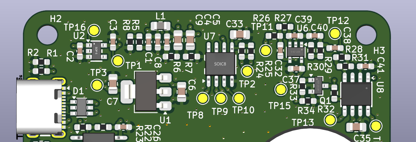
And here is the final PCB layout of the audio circuitry:

Stay tuned for more updates on the Catchcam project!
Note: If you’re interested, you can pre-order a sample at vnucec.ivan@gmail.com.

