
Arty A7-35T Vivado Blinky Tutorial
Here’s a complete step-by-step guide to create a simple blinky LED project (the FPGA “Hello World”) for the Digilent Arty A7-35T (Artix-7 XC7A35T) using AMD/Xilinx Vivado (works with 2022.x–2025.x versions).
Add Artix-7 Support
If Artix-7 devices (like the XC7A35T on your Arty A7-35T) are not installed by default:
- From inside Vivado:
- Open Vivado.
- Go to the top menu: Help → Add Design Tools or Devices.
- The Xilinx Unified Installer will launch in “Add” mode.
- In the installer:
- Proceed through the screens until you reach “Select Devices” or “Select Extra Content”.
- Under FPGA Families (or 7 Series), make sure Artix-7 is checked.
- Click Next and let it download + install the missing device files (this can take 10–30 minutes depending on your internet).
- After installation finishes, restart Vivado completely.
Create a New Project in Vivado
- Create New Project
- Open Vivado → Create Project
- Project name: e.g.
arty_blinky - Project type: RTL Project
- Check Do not specify sources at this time
- Select the FPGA Part Manually
- In the Default Part screen, stay on the Parts tab (do not go to Boards).
- In the search/filter box, type:
xc7a35ticsg324-1L - You should now see this exact part:
- xc7a35ticsg324-1L (Artix-7, speed grade -1L, CSG324 package, industrial temp)
- Select it and click Next → Finish
This is the correct and exact FPGA mounted on the Arty A7-35T.
- Finish the wizard.
Add the Clock and LED Constraints
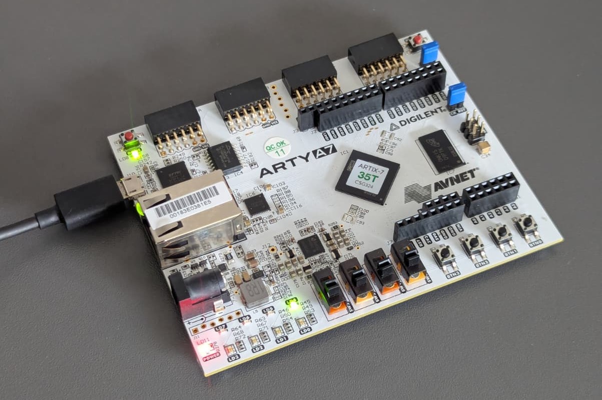
The Arty A7-35T has a 100 MHz single-ended clock on pin E3 and Green LED4 diode on pin H5.
This can also be seen in arty_a7_sch.pdf schematic file.
Create a new file: File → Add Sources → Add or create constraints → name it arty.xdc.
Paste the following into the .xdc file (you can also download the full master file from Digilent’s GitHub):
## Clock signal
set_property -dict { PACKAGE_PIN E3    IOSTANDARD LVCMOS33 } [get_ports clk]
create_clock -period 10.000 -name sys_clk_pin -waveform {0.000 5.000} [get_ports clk]

## LEDs
set_property -dict { PACKAGE_PIN H5    IOSTANDARD LVCMOS33 } [get_ports led]   ;# LD4 (green)
Create the Blinky HDL Code
File → Add Sources → Add or create design sources → create a new file called blinky.v (Verilog).
module blinky (
   input  wire clk,      // 100 MHz clock
   output reg  led       // LED output
);
   reg [26:0] counter = 0;   // ~1.34 seconds period on 100 MHz

   always @(posedge clk) begin
      counter <= counter + 1;
      led     <= counter[26];
   end
endmodule
Generate Bitstream
- Click Run Synthesis → OK.
- After synthesis finishes, click Run Implementation → OK.
- After implementation, click Generate Bitstream → OK.
(This may take a few minutes the first time.)
Program the Board
- Connect the Arty A7-35T to your PC with a micro-USB cable (J10 – the PROG/UART port).
- In Vivado, open Open Hardware Manager → Auto Connect.
- Right-click your device (
xc7a35t_0) → Program Device. - Select the generated
.bitfile (usually inarty_blinky.runs/impl_1/blinky.bit). - Click Program.
You should see LD4 (green LED) blinking slowly with period of 1.342 seconds (100 MHz → 10 nanoseconds clock cycle → 2^26 × 10 ns ≈ 0.671 seconds → 2 × 0.671 s ≈ 1.342 seconds).
Hardware Manager says “unconnected” + no device shows up
Hardware Manager says “unconnected” + no device shows up: Vivado has not opened a connection to the actual hardware target (the Arty board via JTAG).
Because no target is open, the Program Device button stays grayed out.
To overcome it, I ran this command on my Linux machine:
sudo <vivado_install_path>/AMD/2025.2/Vivado/data/xicom/cable_drivers/lin64/install_script/install_drivers/install_drivers
After succesfull install, make sure to reconnect the boards USB and run Auto Connect again.
Blinky stopped blinking after a board power reset
The Arty A7-35T (like almost all FPGAs) has volatile configuration memory.
When you click “Program Device” in Vivado Hardware Manager, you are loading the bitstream directly into the FPGA’s internal SRAM (volatile memory) which is lost when FPGA loses power. When you power it back on → the FPGA starts empty (unconfigured). No logic is running, so the LED stays off.
This is expected behavior for all FPGA development boards when you only do JTAG programming (the default “Program Device”).
How to make blinky survive power cycles
You need to permanently store your bitstream in the non-volatile SPI Flash memory on the Arty board.
The FPGA is designed to automatically load the configuration from this flash chip every time it powers up.
Quick steps to program the flash
- Enable binary file generation:
- Under PROJECT MANAGER (left sidebar) click on Settings
- Go to Project Settings → Bitstream
- Check -bin_file* option
- Apply and re-generate the bitstream. You will now have a
blinky.binfile.
- Add the Configuration Memory Device:
- Right-click on the FPGA device (
xc7a35t_0) → Add Configuration Memory Device. - In the search box, type
mt25ql128. - Select: mt25ql128-spi-x1_x2_x4 (this is the correct flash chip on Arty A7-35T).
- Click OK.
- Right-click on the FPGA device (
- Create and program the flash:
- Right-click on the newly added flash device → Program Configuration Memory Device.
- In the dialog:
- Browse to your
.bitfile (usually.../impl_1/blinky.bit). - Click OK and wait (this takes 1–3 minutes).
- Browse to your
- Power cycle the board:
- Unplug the USB cable.
- Plug it back in.
Wait for a few seconds for FPGA to load bitstream from the flash and your LED should now start blinking automatically on power-up, without needing to reprogram via Vivado.