
Arty A7-35T Vivado MicroBlaze Tutorial
Here’s a complete step-by-step guide to create and run a MicroBlaze soft processor on the Digilent Arty A7-35T (Artix-7 XC7A35T) using AMD/Xilinx Vivado 2025.2 and Vitis Unified Embedded IDE 2025.2.
This tutorial will guide you through building a simple MicroBlaze system with UART communication and running the classic Hello World application.
Vivado Project Creation
- Open Vivado 2025.2
- Under Quick Start, select Create Project
- Enter a project name (e.g.
arty_microblaze) and choose a location, then click Next - Select RTL Project, uncheck Do not specify sources at this time if needed, and click Next
- On the Default Part screen, switch to the Boards tab
- Search for “Arty A7-35”
- Select Arty A7-35 and click Next → Finish
Creating the Block Design
- In the left sidebar, under IP INTEGRATOR, click Create Block Design
- Accept the default name (
design_1) and click OK
Adding the MicroBlaze Processor
- Click the + button in the diagram to add a new IP
- Search for “MicroBlaze” and double-click it to add the IP
- Click Run Block Automation
- Set Local Memory to 64 KB
- Leave other options at default and click OK
- Run Block Automation again and accept the defaults
- Click Run Connection Automation and select All Automation → OK
Configuring the Clock
- Delete the diff_clock_rtl external port (right-click → Delete)
- Double-click on the clk_wiz_1 IP block
- Set CLK_IN1 to sys clock
- Click OK
- Run Connection Automation again and click OK
Why configure the clock?
The Arty A7-35T has a 100 MHz single-ended clock source on the board. By deleting the differential clock port and telling the Clock Wizard to use the board’s “sys clock”, we correctly connect the FPGA to this 100 MHz clock. MicroBlaze and all the peripherals (like UART) need a stable clock to operate.
Adding UART
- Click the + button and search for “AXI Uartlite”
- Double-click to add it
- Run Connection Automation and select All Automation → OK
Create HDL Wrapper
- In the Sources tab, expand Design Sources
- Right-click on design_1 (design_1.bd) → Create HDL Wrapper
- Leave default settings and click OK
Why create an HDL Wrapper?
The Block Design is a graphical representation of your system. Vivado needs a traditional HDL (Verilog/VHDL) file that “wraps” this block design so it can be synthesized into a real bitstream. The wrapper automatically generates this top-level HDL file for you.
Generate Bitstream
- In the left sidebar under PROGRAM AND DEBUG, click Generate Bitstream
- A popup will appear asking to run synthesis and implementation — click Yes
- Set the number of jobs (according to your CPU cores) and click OK
- Monitor progress in the Design Runs tab at the bottom
- Once finished successfully, click Cancel to close the dialog
Export Hardware Platform
- Go to File → Export → Export Hardware
- Click Next
- Select Include bitstream (important!)
- Leave the default path and click Next → Finish
Why export the hardware platform?
The.xsafile (Xilinx Shell Archive) contains all the information Vitis needs to know about your hardware: which processor is used (MicroBlaze), what peripherals are connected (UART), memory map, clock settings, and the bitstream itself. This file acts as the bridge between the hardware you designed in Vivado and the software you will write in Vitis.
Creating the Software Application in Vitis
1. Launch Vitis IDE
- In Vivado, go to Tools → Launch Vitis IDE
2. Create New Platform Component
- In Vitis, under Embedded Development, select New Platform Component
- Give it a name (e.g.
arty_microblaze_platform) and choose a location - Browse to the exported
.xsafile (usually in your Vivado project folder) - Click Next
- Set Operating System to standalone
- Set Processor to microblaze_0
- Click Next → Finish
Why create a new Platform Component?
The Platform Component tells Vitis exactly what hardware your software will run on. It imports the.xsafile and generates all the necessary drivers, header files, and memory maps automatically. Without it, Vitis wouldn’t know how to talk to the MicroBlaze processor or the UART peripheral.
3. Create New Application Component
- Go back to the Welcome tab
- Under Embedded Development, select New Application Component from Example
- Click the + button next to the “Hello World” template
- Give the application a name (e.g.
hello_world) - Select your newly created platform
- Click Next → Finish
Inspecting the Hello World Code
You can view the source code by expanding your application in the left sidebar by opening Sources → src → helloworld.c.
The contents of the helloworld.c file are as follows:
#include <stdio.h>
#include "platform.h"
#include "xil_printf.h"

int main()
{
    init_platform();

    print("Hello World\n\r");
    print("Successfully ran Hello World application");

    cleanup_platform();
    return 0;
}
Building and Running on Hardware
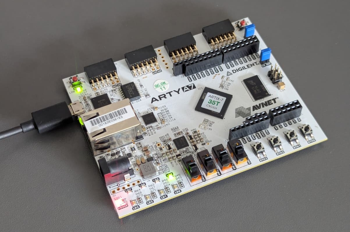
- Connect the Arty A7-35T to your PC using the micro-USB cable (J10 – PROG/UART port)
- In the Flow tab (or toolbar), click Build to compile the application
- Once the build finishes, click Run
- Open a serial terminal program (PuTTY, Tera Term, minicom, etc.) on your PC
- Port: the COM port assigned to the Arty board
- Baud rate: 9600
- Press the RESET button on the Arty board
You should see the following output in your terminal:
Hello World
Successfully ran Hello World application
Congratulations! You now have a working MicroBlaze soft-core processor running on your Arty A7-35T with UART communication.